In this paper we describe a Python- and Tkinter-based visual-programming environment called ViPEr. This tool enables non-programmers to build computational and visualization networks interactively. Computational nodes can be placed onto a canvas and their input and output ports can be connected using the mouse. The connections between the nodes define a directed graph that will be used to propagate data and trigger the execution of nodes that have new input data. ViPEr is, in appearance, similar to programs such as AVS [Upson et al. 89] from Advanced Visual Simulations Inc, or OpenDX [DX 93] from IBM, but presents some fundamental differences which will be pointed out throughout this paper. Several examples of applications will be used to illustrate ViPEr's design and current range of capabilities.
The focus of our laboratory is the modelisation of molecular interactions. We are working on several aspects of this problem, including molecular visualization, protein-ligand docking, protein-protein docking, molecular surfaces, phenomenological potentials, etc. The methods we use in our models come from fields as diverse as computational chemistry and biology, computational geometry and augmented reality. We have been using Python as a platform to develop re-usable and inter-operable components dealing with different aspects of structural bioinformatics [Sanner 99a, Coon et al. 01, Python at TSRI]. These components are the basic building blocks from which several domain specific applications have been developed. These include a generic molecule visualization program (PMV [Sanner 99a, Coon et al. 01]), a viewer for volumetric data (PVV) and a graphical user interface to our molecular docking program AutoDock [Coon et al. 01]. These applications have demonstrated a great deal of flexibility, extensibility and code re-use and have been distributed to over 200 laboratories around the world. They all expose the underlying Python interpreter, providing a fully-fledged programming language to operate, both over the data structures in the application, and the application itself. However, we have found that this capability is seldomly used, because it requires learning the Python programming language and becoming familiar with the data-structures used in the applications. This is often beyond the level of investment a typical user is willing to make. On the other hand, we realize that it is impossible to anticipate all uses and combinations of the components that we have developed, or to implement all possible commands users are ever going to want. To address this problem we developed a visual programming tool that enables non-programmers to intuitively and interactively build networks describing new computational streams and novel visualizations of their data, without having to write code or understand the details of the application's data structures. This development was partly motivated by our previous experience with the data-flow environment AVS [Upson et al. 89] that has been used successfully in our laboratory for over 10 years [Macke et al. 98].
AVS provides an environment in which components (also called modules) are connected to create a computational pipeline. It is comprised of a large number of processing modules for a wide variety of operations. Custom modules can be added to extend the environment with new computational methods. The modular nature of AVS provides a good level of code re-use as modules, once written, can be shared with other AVS users. Moreover, its modular nature fosters the compartmentalization of computational tasks. However, we also experienced some serious limitations, which prompted us to gradually develop our own Python-based set of components to deal with our visualization needs. These limitations include: 1) the "self-centric" nature of AVS, i.e. AVS is the program in charge, deciding what, when and how things happen, 2) the amount of overhead to add new nodes to AVS; porting new computational methods to AVS is a non-trivial task reserved to "hardcore" low-level programmers and the resulting module is only usable within AVS, 3) the rigidity of AVS predefined data types, 4) the duplication of the data as it flows through a network and 5) the lack of programmability of AVS itself. In an early attempts to address these problems we embedded a Python interpreter into an AVS module enabling the creation of new modules written as a Python script [Sanner et al. 99b]. We found however, that this was really stretching AVS's capabilities and was still unsatisfactory in several aspects. The software development strategy we have developed over the past few years is entirely based on Python for the development of components and using Python as the "glue" to connect these components at a high level in order to produce end-user applications. This approach has been very successful so far, but in the process we lost the ability for non-programmers to interactively build networks describing novel combinations of computational methods, and yielding new visualizations of their data without actually writing code. This capability is of particular interest in our community where the typical users are biologists and chemists who often do not want to, and really should not have to become programmers in order to manipulate and visualize their data.
In this paper we present a Python-based network editor providing functionality similar to AVS' network editor (figure 1). A first package called NetworkEditor implements the basic objects needed to build a network. The NetworkBuilder class defined in this package provides support 1) for creating networks of connected nodes and 2) for the graphical representation of such a network. An interactive version of that builder adds support for creating nodes and connecting them with the mouse. The ViPEr package extends this interactive network builder with: 1) the ability to organize nodes into libraries that are displayed in the user interface, 2) drag-and-drop support for adding nodes to a network and 3) the simultaneous manipulation of multiple, and possibly nested, networks. Nodes in a network have input ports providing data to the node's computational function and output ports enabling a node to provide data to children nodes. The color and shape of these ports is indicative of the type of data that is expected or provided. A fundamental difference with most other similar environments is that ViPEr has no data type restrictions and any entity available in a Python interpreter can be passed from one node to another. In addition, the data is passed by reference whenever possible, often avoiding its duplication. Connections from output ports to input ports define a directed graph, which is used to propagate data and trigger the execution of nodes that have new input data. ViPEr comprises a set of standard nodes including a 3D-visualization node. Besides this standard library we have developed several more libraries some of which we will describe in this paper. ViPEr nodes are essentially lightweight wrappers of functionality that is otherwise available in Python. They are easy to write and new nodes can be created interactively during a working session. This is an important difference with other environments such as AVS or OpenDX, where adding a node is often complex and the result is only usable within this environment. Our approach has enabled us to rapidly expose most of our previous work [Coon et. al 2001] in ViPEr.
Networks built using ViPEr can be saved as Python code into files. The network is loaded back into ViPEr by executing the Python code contained in this file. This approach avoids having to invent a network file format with its limitations and arbitrary choices and instead provides us with a powerful, flexible and general purpose programming language to describe networks. Sub-networks can be encapsulated into macro nodes, enabling the nesting of networks. A node editor assists the creation and debugging of new nodes, minimizing the amount of code that has to be written. Tooltips provide runtime information about node functions, inputs and outputs. Data flowing through connections can be interactively monitored and introspected. A data type manager holds a pre-defined set of data type objects and new types can be added to this table interactively. Although data types are optional, by declaring one, it is possible to specify the appearance (color and shape) of the port's icon. This provides helpful visual hints for connecting the proper outputs to the proper inputs.
In the following sections we will introduce ViPEr's basics using a short tutorial, describe the creation of nodes and macro nodes, present a set of new Tkinter widgets and the pre-defined data types, and demonstrate the creation of a node library. A short discussion of the current implementation and open issues will precede our conclusion.
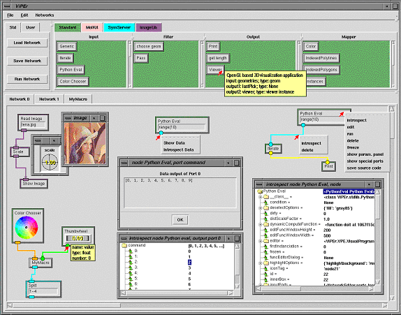
When ViPEr is started, the graphical user interface (GUI) shown in figure 2 is displayed. This interface provides paned widgets for menu-bars, buttons, node libraries, and network canvases. The node libraries are color-coded and organized into categories that appear as scrolled widgets containing nodes. For instance the standard library has the following 4 categories: Input, Filter, Output and Mapper. If the mouse cursor is left for a while (hovering) on top of a node's icon in a library, a tooltip appears with the node's documentation. This is shown in figure 2 for the Viewer node in the Output library. A node can be added to a network by dragging and dropping it from the library to the network's canvas. As the node is added to the network, icons for its input and output ports and potential widgets are created. The rim of the node's icon has the same color as the library it originated from. The shape and color of each port is defined by the port's data type. The 'Python Eval' nodes have a green rim matching the standard library's color. They have a type-in widget for specifying the Python statement to be evaluated and output their results to an output port that appears on the bottom edge of the node. The thumbwheel node in the lower left network shows how hovering the mouse cursor on top of a port icon displays a tooltips for that port. The port's name and data type are reported along with an optional data type description, an optional port description, and the port's number. Input ports tooltips also tell whether or not this port is required to provide data for the node to run. The data type can be 'None' for ports accepting any type of data.
Output ports of a node can be connected to input ports of other nodes. This is done by clicking on an output port (left mouse button) and dragging the mouse cursor to the desired input port. A green rubber-band line appears between the output port from which the connection originates and the mouse cursor. When the mouse gets close to an input port, the rubber-band line will snap to that port. When the mouse button is release, a connection is created if the end of the rubber-band line is connected to an input port. Note that we do not prevent any given connection from being created. Mismatches between the data types of connected ports will be caught during the execution of the network.
Input data to a node can also be provided by widgets bound to an input port. Such widgets appear either inside the node's icon or in the node parameter panel. For instance the "Read Image" node in figure 2 has a "NEEntryWithFileBrowser" widget appearing in the node and bound to its unique input port. These widgets enables a user to type a file name directly or, by double-clicking on the input field, use a file browser to specify the file to be read. The Scale node scaling the image uses a dial widget to specify the scaling factor. This dial appears in the node's parameter panel as shown in figure 2. Double clicking on the node toggles the visibility status of this parameter panel. By default, nodes share the window displaying the node's parameter panels. Double-clicking on another node than Scale in our example would replace the Scale node's dial widget with the widgets of that other node. ViPEr has an extensible set of widgets that will be described later. When a widget is bound to an input port, the port's icon does not appear on the node's graphical representation as it is no longer a candidate to receive data from another node in the network. For instance the filename input port of the 'Read Image' node shown in figure 2 is bound to a type-in widget which appears in the node.
Once connections have been created we have a network which can be executed or saved to a file. Every time new data is presented to a node, this node is scheduled for execution. For each of its input ports the data type and the data validation function (if any) are obtained. A loop over all connections to the port collects the port's data. During this loop, the data provided by each connection is validated and valid data is merged into one object. If the data type is a Numeric array, data from different parents is concatenated. If the data implements a list interface, the data from different parents is merged into a single list. Otherwise the data from each connection is appended to a list. If invalid data is found for one of the connections or a required port does not receive any data, the process stops, the node's function is not called and children nodes are not scheduled. Else, the data found for each port is passed as arguments to the node's computational function. If this function completes successfully, the sub-tree of its children nodes is scheduled for execution. This is done by building a list of nodes-to-be-run corresponding to a breadth first traversal of the sub tree. This will avoid the premature execution of a child node by making sure that any parent node has been executed before. Since this list only changes when connections are created or deleted, we cache this list. We have also implemented a multi-threaded version of the scheduling mechanism in which each node runs in a separate thread. This approach however, currently requires the data structures being passed through the nodes to be thread-safe. It is possible to freeze a node to temporarily disable its execution. An entire network can be executed using the "run network" button. To achieve this, the network editor maintains a list of root nodes, i.e. nodes having no parents.
Clicking with the right mouse button on any node, connection or port will display a pulldown menu for the corresponding item (see figure 2). For ports, this menu provides the ability to 'show' and 'introspect' the data. The 'Show Data' entry will open a data window for this port presenting a string representation (as obtained by the repr function) of the data currently available on that port. This window is dynamically updated every time the node is run. The 'Introspect Data' entry will open an object-browser window enabling the introspection of the data available on the port. The data object will be displayed as a node that can be recursively expanded to reveal all its attributes. The menu obtained by right-clicking on a connection provides entries to introspect or delete a connection. A node's menu has commands to introspect, run, delete, freeze/unfreeze and edit the node. When a node is deleted, all its connections are deleted too. The "edit" entry will open a node editor. This editor will be discussed in the next section. Freezing a node will prevent its execution along with the execution of any children nodes.
The network editor maintains a list of selected nodes and connections. The selection state of nodes can be toggled by dragging a box around a set of nodes (left mouse button). Selected nodes in the box will be deselected and deselected ones will be selected. Selected nodes can be deleted using the delete menu entry from the 'Edit' menu found in the menu bar at the top of the user interface. They can be moved (middle mouse button) or scaled (Shift and middle mouse button). The canvas can be scrolled using the scroll bars or by 'grabbing' the canvas using the right mouse button.
1)	class ReadImage(NetworkNode):
2)	    """based on the Image.open function. Reads an image file
3)	       Input:  filename (string)
4)	       Output: Image"""
5)
6)	    def __init__(self, name='Read Image'):
7)
8)	        apply( NetworkNode.__init__, (self,), {'name':name})
9)	        self.readOnly = 1
10)
11)	        self.inputPortsDescr.append(
12)	               {'name':'filename', 'datatype':'string'} )
13)
14)	        self.outputPortsDescr.append(
15)	               {'name':'image', 'datatype':'image' })
16)
17)	        self.widgetDescr['filename'] =
18)	               {'class':NEEntryWithFileBrowser,
19)	                'master':'node',
20)	                'filetypes': [('all', '*')],
21)	                'title':'read image',
22)	                'width':10 }
23)
24)	        code = """def doit(self, filename):
25)	                      import Image
26)	                      im = Image.open(filename)
27)	                      if im: self.outputData(image=im)\n"""
28)
29)	        self.setFunction(code)
Line 1-8: NetworkNode is sub-classed to create a "read Image" node. The class documentation string will be exposed in the tooltip for that node.
Line 9: This node will not be editable. The user will be able to look at the source code of the functions but won't be allowed to modify it. In order to alter the node's behavior he would have to clone the node and edit the copy.
Lines 11-12: Definition of the only input port of this node: 'filename'. The name of this port has to match the argument of the function (line 24). This port will be required by default. In order to make it optional, one would have to add 'required':0 to the port's description. The type of data expected by this port is 'string', which is a pre-defined data type in ViPEr.
Lines 14-15: Definition of the only output port 'image'. The name of this port has to be used as the argument name when data is output (line 27). This port will output data of type 'image'. This type is defined by the library containing this node and is added to the editor's types table when the library is loaded.
Lines 17-22: Definition of a widget of type "NEEntryWithFileBrowser". This is a Tkinter Entry widget for which double clicking brings up a file browser. Line 19 specifies that this widget should appear inside the node rather than in the node's parameter panel. Since this widget's name matches the name of the input port, it will be bound to this port and the port's icon will not be displayed.
Lines 24-27: Definition of the computational function with one argument "filename".
Line 29: The string code is compiled and set as the function to be called when the node runs. This example illustrates the fact that a network node really is a lightweight wrapper of functionality otherwise available in Python. The computational function is very short and easy to write. An experienced ViPEr user can easily write the code for such a node. Most of this code can also be generated using ViPEr's node editor [figure 3].
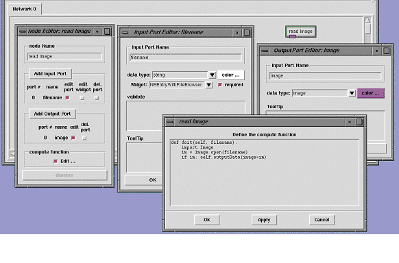
This editor can be accessed using the 'edit' entry of the node's menu. The node editor can be used to rename the node, add/remove input and output ports, edit ports, and define/modify the computational function. To create the node described above, we could start from a generic node found in the standard library and rename it 'Read Image' in the node editor. We would then add an input and an output port using the same node editor window. Clicking on the 'edit' button next to the port's names would display the two port editors. These editors let us rename the ports to 'filename' and 'image' respectively and bind an NEEntryWithFileBrowser widget to the 'filename' input port.
The node editor automatically updates the signature of the computational function as input ports are added or removed. It will also provide the line of code used to output data to the existing output ports. The 'Edit �' button in the compute function section of the port editor lets us display the function skeleton created by the node editor. In this window we only have to type two missing lines of Python code (lines 25-26 in the previous example) and replace 'result' by 'im' in the last line of code (line 27 in the example). After a node has been edited, its menu has a new entry called "save source" enabling to save the code describing this node. The code generated by this command would be identical to the code described earlier in this section. This capability of generating a node's source code is used in particular to save modified nodes when a network is saved to file. When this network is loaded again, the edited node is created not from the original node object found in the library, but from the custom node saved in the file hence providing all modifications.
The node editor can be used to inspect any node, but only non read-only nodes can be modified. Writing a new node comes down to defining its input and output ports, potential define widgets and define what the node should do.
A macro node corresponds in some sense to a function in ViPEr. Such a node encapsulates a sub-network, which can be visualized and edited by double clicking on the macro node's icon.
A macro node is created using the "create macro" menu entry from the "Edit" menu. A new canvas named after the macro is added to the canvas notebook and a node named after the macro appears in the current network (figure 4). The canvas holding the macro's network contains two special nodes labeled "input Ports" and "output Ports" each having a special port. These two nodes allow nodes from the parent network to be connected to nodes in the macro. The macro's network of nodes is created just like an ordinary network except for connections to the special ports which will behave differently. For instance, in order to receive data from the parent network, the input port of a node in the macro network has to be connected to a port of the special node named "input Ports". Initially the special node has only its special port to choose from. When such a connection is made, a new port for this connection is added to the special node such that the special port remains free. At the same time, an input port is added to the macro node in the parent network. A second node in the macro network that wants to receive data from the parent network can now be connected to the same port (on the special node) as the previous node in which case it will get the same data. Alternatively it can be connected to the special port, thus creating its own input port on the macro node in the parent network. The special output port behaves the same way.
We have mentioned earlier that input ports can be bound to widgets. ViPEr provides an extensible set of widgets ranging from a simple Tkinter Entry widget to a color map editor and a 3D vector browsing widgets. In this section we will list and describe ViPEr's standard widget set. These widgets are shown in figure 5.
All widgets in ViPEr inherit from the PortWidget base class. They are a class on their own since they need to implement a uniform interface used by the network editor to create, configure, query and save them. The NEEntryWithFileBrowser can be used to specify filenames. It has a Tkinter Entry in which a file name can be typed. Alternatively, one can double-click on the entry in order to display a file browser to choose a file to be opened. NECheckButton is the ViPEr wrapper around the Tkinter Checkbutton, NEEntry wraps the Tkinter Entry and NEComboBox wraps the Pmw ComboBox widget.

Widgets that were not already available in Pmw or Tkinter, such as dials, thumbwheel, color map editors, etc, we developed our own. These new widgets were written using Tkinter and are independent of the ViPEr environment. They have all been wrapped for ViPEr under the following names: NEDial, NEThumbWheel NEVector3DBrowser, NEColorChooser, NEColorMapEditor. These also exist as individual nodes in the standard library.
The dial widget implements a handle that can be moved around in a circle (Fig. 5). Many options can be set to alter this widget's behavior. These options are exposed in the dial's configuration panel shown in figure 5. This panel can be displayed by right clicking on the widget. The continuous option can be set to 'on' or 'off'. When it is on, callback functions will be called at every value change. When it is set to 'off' the functions will only be called when the mouse button is released. The minimum, maximum and increment check buttons enable to turn on or off constraints on the range of
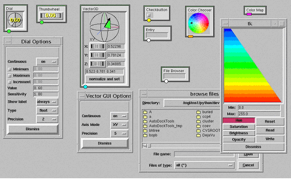
values the dial can reach. When any of these check buttons is checked, the entry widget to their right becomes activated enabling a user to specify a value for that particular restriction. The value entry widget can be used to set the widget's value directly. The sensitivity entry specifies the range corresponding to a full turn of the handles. 'ShowLabel' can be set to 'never', 'always' or 'move'. This option controls how often the digital representation of the current value appears on top of the widget. In figure 5 the dial widget shows the value, while the thumbwheel does not. The dial's 'Type' can be switched between 'float' and 'int' and for floating point values, the precision pull-down allows selecting the number of decimals used to display the value in the widget. In addition to these parameters that can be modified at run time, there are some that can only be specified at the object's instanciation. These include the dial widget's size and various locks preventing some options from being exposed to the viewer in the widget's parameter panel.
The ThumbWheel widget is a sibling of the dial widget. It has the same options except for 'size', which is replaced by a 'width' and 'height'. It has the same parameter panel as the dial widget.
3DVectorBrowser is a rather specialized widget in which a graphical representation of a 3D vector can be rotated with the mouse. This widget produces an (x,y,z) vector. The vector can also be rotated along the Y, Y and Z-axis independently, using the 3 thumbwheels found below the vector. Vector values can also be typed in directly. The 'continuous' and 'precision' options in this widget's option panel have the same meaning as for a Dial. The 'Axis Mode' option controls how the mouse motion is used to modify the vector.
All these widgets are able to provide their own description. This feature is used by ViPEr to save a network and to re-configure all widgets when the network is loaded later.
As we mentioned earlier, ViPEr does not impose any rules or restrictions on data types. However, we found that visual hints providing some information about the type of data are very valuable for users to make the right connections. For this reason we added a type manager object to ViPEr. This object is a repository of type objects. A type object provides a name for the type, a shape and a color to be used for the icon of ports having this data type, an optional data description string that will be added to the tooltip and an optional validation function. The default type is called 'None' and its validation function is None, meaning that no type checking will be done for this data type. The color has to be a Tkinter color string and the shape can be any string in the following list: 'circle', 'rect1', 'rect2', 'oval1', 'oval2', 'diamond', 'triang1', 'square', 'pentagon' and 'hexagon'. The 'rect1' and 'oval1' shapes have their longer dimension aligned horizontally while 'rect2' and 'oval2' have it aligned vertically.
In order to provide some visual consistency we have defined types organized from 0 dimension (0D, i.e. single values) to 6 dimensional arrays for a number of data types. We have used the shape to code the dimensions using 'circle' for 0D, 'diamond' for 1D, 'oval1' for 2D, 'triang1' for 3D, 'square' for 4D, 'pentagon' for 5D and 'hexagon' for 6D arrays. The colors code the types using the following scheme: yellow for int and long, green for float and double, white for string, brown for complex, cyan for arrays, list and tuple, and blue for dictionaries. Any such type is named 'xDtype' where x ranges from 0 to 6 and type is one of the basic Python data types (int, long, float, double, array, list, tuple, dictionary). For types starting with 0D we have defined aliases in which we stripped the 0D part.
Finally we added custom types such as 'geom' and 'viewer' for DejaVu geometries and viewer objects [Coon et al. 01], and 'coordinates3D', 'normals3D', 'colorsRGB' and 'colorMap'. These last four types, all represent 2D arrays of floating point values, but we wanted to have distinctive icons on the nodes to help visualize what are the right connections to be made between nodes. Users can specify additional types if necessary.
As we have seen before, nodes are organized in libraries, each defining its categories. In order to create a new library one needs to create an instance of the NodeLibrary class. The constructor of this object accepts a name for the library and an optional color (line 1 in the code below). Nodes can be added to the library using the addNode method of the NodeLibrary instance. In line 2 we add the node defined earlier with the name 'Read Image' in the category 'input'. Such a library object can then be added to ViPEr using the showLibrary(newlib) method.
1)	newlib = NodeLibrary('mylibrary', '#AAEECC')
2)	newlib.addNode(ReadImage, 'Read Image', 'input')
A library can also define new data types that are specific to this library. For instance the ImageLib library defines an "image" data type, a color and a shape for ports passing an image object and a validation function. Code to define this type and to add the type to the library is shown below. When the library is added to ViPEr, the libraries specific types are added to ViPEr's data type manager.
3)	class ImageType(AnyType):
4)	    def __init__(self):
5)	        self.name = 'image'
6)	        self.color = '#995699'
7)	        self.shape = 'rect1'
8)	    def validate(self, data):
9)	        import Image
10)	        return isinstance(data, Image.Image)
11)
12)	 newlib.typesTable.append( ImageType() )
In the same way, a library can add its own set of widgets to the set available in ViPEr. After new widgets have been added they become visible in the pull down menu of the port editor enabling a user to bind them to ports.
ViPEr's standard library contains application independent nodes. In this section we will describe some of them by categories.
We have created a set of nodes exposing some capabilities of the Python Imaging Library (PIL) in ViPEr. Most of the nodes are self-explanatory. They expose a small subset of PIL's capability and new ones will be added, as they are needed.
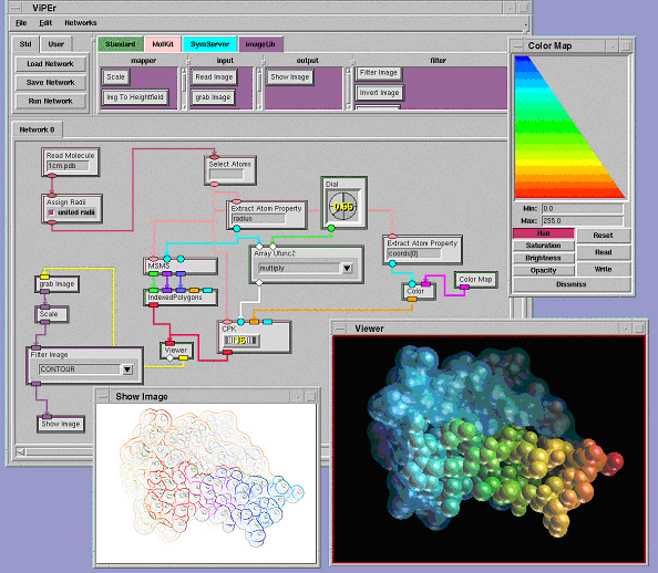
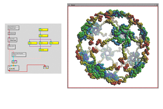
This library also provides a node to grab the frame-buffer and one to grab the Z-buffer of 3D-geometry viewer created by a Viewer node. This provides an intuitive way to build a processing stream that applies to the image resulting from rendering a 3D scene as shown in figure 1. This library currently defines the data type 'image' described earlier.
MolKit is our component to read, write, represent, and query molecular data structures. It is written entirely in Python and represents molecules as hierarchical structures [Coon et al. 01]. We have exposed some of its capabilities in ViPEr. Read Molecule reads a molecular data file and outputs a MoleculeSet instance. Assign Radii assigns a radius to every atom of the incoming MoleculeSet. Select Atoms selects subsets of atoms by matching a user defined regular expression with atomic names. The selected atoms are output as an AtomSet instance. Bonds By Dist. computes atomic connectivity based on atomic distances. The created bonds are added to the Molecule objects of the incoming MoleculeSet instance. The CPK node builds a DejaVu.Spheres geometry holding one sphere per atom. The MSMS node uses another Python extension (mslib) that wraps a library written in C for computing solvent excluded molecular surfaces [Sanner et al. 96]. This node outputs the description of the surface's geometry: 3D vertices, triangle indices and vertex normals. This information can be turned into a geometry object using the IndexedPolygons node from the standard library (figure 1). The Extract Atom Properties node takes a list of atoms, extracts a user specified attribute from each atom, and outputs the list of extracted attributes. The string specifying the attribute to extract supports simple indexing into sequences and dictionaries. In the network shown in figure 1 we use this node to obtain the X-coordinate of each atom. This list of floating point values is then converted into a list of colors using a color map ranging from blue to red. The resulting colors are sent to the CPK node to color the spheres. This library defines several new data types such as 'Atom', 'AtomSet', 'Molecule' and 'MoleculSet'.
This library implements a set of nodes defining geometric transformations including 2, 3, 4, 5, 6, and N-fold symmetries, translation, rotation, helical arrangements, etc. These nodes can be combined in tree-like structures to create streams of 4x4 matrices describing complex hierarchical symmetries such as an icosahedral symmetry. This stream of matrices can be applied to any geometry displayed in a viewer. When instance matrices are specified for a DejaVu geometry, the geometry's display list is executed once with each instance matrix on the OpenGL transformation stack. The nodes in that library mainly deal with data of type 'instanceMatrices'.
Besides nodes generating geometrical transformations, this library also provides a Split node to split the stream of matrices. This node supports the specification of comma-separated list, and ranges. Multiple splits can be specified using a semi-colon separator. For instance, "3-6,8,12; 9-11" would add two additional output ports. The first output port (starting from the left), would output all matrices from the incoming stream except for the ones split. The second port would output matrices 3, 4, 5, 6, 8 and 12. The thirds port would output matrices 9, 10 and 11. This feature can be used for instance to apply additional transformations to a subset of the matrices before merging the streams back together with a Merge node.
ViPEr is build on top of a package called the NetworkEditor. This package defines objects such as NetworkNode, NetworkConnections, Ports, etc. Nodes, connections and ports all are subclasses of NetworkItems. They all have an associated computational function, which means, that connections between nodes could carry out a computation, even though the current implementation of the execution scheduling does not support this feature. NetworkItems can be sub-classed to define new nodes, connections or ports with new behavior. ViPEr is an example of how the NetworkEditor package can be used for visual programming but we expect the NetworkEditor to be usable for other applications. We have chosen Tkinter as the graphical user interface toolkit because in our experience it is still the most portable one. We use ViPEr on Sgi, Sun, Dec Alpha, PCs both under Linux and windows.
Operations such as adding a node, connecting ports, moving nodes, etc, can log themselves, i.e. produce a command line that corresponds to that action. This information can be used to write a log file enabling to play back a session. It also will facilitate the creation of collaborative tools, where such a string description of actions performed on a server will be sent to remote clients in order to reproduce these actions on the clients. ViPEr loads a network from a file by executing the Python code contained in this file. This makes the Python programming language the network description language, or in other words, the network description itself is a Python program. This makes it possible to create "smart" networks.
ViPEr is at a very early stage and there is still a lot to be done as well as a number of issues to be addressed. These issues include the management of data types, better execution flow models, the creation of a web accessible module repository, private module vaults for users, threads supports and automatic data locking data, etc.
Although we have not yet experienced any performance problems, ViPEr's interactive responsiveness can be increased substantially in the future. In the current implementation, when a change in a network triggers the execution of a part of the network, each input port of each node that is run will validate the data provided by each connection to this port. This validation is only needed for new data but currently happens every time a node runs. Likewise, if a node's computational function was able to determine which of its arguments have changed, the function's code could become more efficient by doing a partial calculation updating what is affected by the changes. Moreover, If nodes could output modified data selectively on output ports, the subset of children nodes with new data would trigger, thereby improving the network's performance. There is a lot of room for improvements for the scheduling in general and we have only started to look into that area. Multithreading is definitely an alternative that we need to explore further, along with support for the automatic locking of data that flows through a network.
Another design issue that needs to be addressed is the granularity of nodes. For example a node such as the MSMS node from the MolKit library currently outputs 3D vertices, triangle indices and vertex normals. These are turned into a geometry object using the IndexedPolygons node. Instead of this approach we could have chosen to either output the geometry directly from the MSMS node, or output an MSMS object and provide an additional node to extract the vertices and triangles from that object. There is a trade off between generality and complexity. The first solution where the node outputs a geometry object is obviously less general but makes it easier to build the network and the execution overhead is minimal since there is only one node to be run. The second solution in which an MSM object is output by the node is much more general. With this approach new nodes could be developed to extract any information available in MSMS object and this information could be processed in the network. The drawback however, is the increased number of node: one to compute the surface, one to extract the geometric information and one to create the geometry. The network becomes more complex and there is more execution overhead. The natural solution that comes to mind is a macro node that would encapsulate the sub-network computing the surface. Yet, there is a danger in creating too many nodes as it can become overwhelming for the user.
Future directions also include the separation of the network itself from its graphical representation and the ability to generate Python code corresponding to a network but avoiding the execution overhead.
We have presented a platform independent, Python and Tkinter-based visual programming environment called ViPEr. This environment is based on a more general Python package called the NetworkEditor, which facilitates the visualization of entities and their relationships. ViPEr has many similarities with other visual programming environments but adds a new level of programmability and flexibility. It greatly simplifies adding new nodes including the ability to edit and define nodes on the fly. Nodes are lightweight wrappers of functionality available in Python. This approach encourages a clear separation between the computational method and the node exposing this method within a network. The added benefit of that separation is that the computational methods ported to Python can be used outside the context of a network. By describing networks as Python programs rather than using our own format, 'intelligent' networks that use all of Python's capabilities can be created. Since ViPEr it is written in Python it integrates tightly with all the other software development efforts in our laboratory and it leverages extensively previous developments.
Even though ViPEr is still at an early stage, it has already been used as a graphical user interface to several Python components that we use in our daily work. It provides an alternative user interface to functionality we have developed earlier and exposed in end-users programs such as the Python Molecule Viewer (PMV). In fact we have started integrating ViPEr into PMV because the type of interface ViPEr provides is better suited for some tasks than a PMV command. For instance, building an image processing stream, or building a hierarchy of symmetry operators is very natural in ViPEr while it would be awkward to say the least, in PMV.
Finally, ViPEr is an example of using the NetworkEditor package for creating a visual programming environment. We are designing the NetworkEditor for the more general problem of the visualization of entities and relationships between these entities. In Viper these entities are compuaional methods and the relationships define a data flow through a network. But we envision using this technology for many other tasks such as querying graphically SQL databases or visualizing metabolic pathways.
[Coon et al. 00] Sophie I. Coon, Michel F. Sanner and Arthur J. Olson. Re-usable components for structural bioinformatics. In Proceedings of the 9th International Python Conference. Xx-xx (2000)
[DX 93] Technical Report, ICM Corporation, p. various, February 1993
[Macke et al. 98] Thomas J. Macke, Bruce S. Duncan, David S. Goodsell and Arthur J. Olson. Interactive modeling of supramolecular assemblies. J. Mol Graph and Model. (1998) 16, 115-120.
[Python at TSRI] http://www.scripps.edu/~sanner/python
[Upson et al. 89] C. Upson et al. IEEE Comput. Comput. Graphics Appl. 9(4), 30-42 (1989)
[Sanner et al. 96] M.F. Sanner, J.C. Spehner, and A.J. Olson. (1996) Reduced surface: an efficient way to compute molecular surfaces. Biopolymers, Vol. 38, (3), 305-320.
[Sanner 99a] Michel F. Sanner. Python: A Programming Language for Software Integration and Development. J. Mol. Graphics Mod., 1999, Vol 17, February. pp57-61.
[Sanner et al. 99b] Michel F. Sanner, Bruce S. Duncan, Christian J. Carrillo and Arthur J. Olson. Integrating Computation and Visualization for Biomolecular Analysis: An example using Python and AVS. Proc. Pacific Symposium on Biocomputing. (1999) pp 401-412.